50 Results
View results:
Sort by:

The automatic surface reinforcement design process determines a surface reinforcement that covers the required amount of reinforcement.

The number of National Annexes for Eurocode 2 with regard to the design of reinforced concrete cross-sections has been extended since SHAPE-MASSIVE 6.54. Therefore, the following NAs of EN 1992-1-1:2004 + AC:2010 are available:

RF-CONCRETE Members also includes the design of a shear joint. In order to perform this design, you should select the "Shear joint available" check box in Window 1.6, Shear Joint tab.

It is possible to edit a reinforcement layout or an existing reinforcement directly in the reinforcement's 3D rendering.

The dialog box for editing load or result combinations is a non-modal dialog box. This means that after you open this dialog box, you can edit the combinations outside the dialog box as well. For manually defining or editing a combination, a separate dialog box can be opened parallel to the "Edit load cases and combinations" dialog box.

When modeling structural bearing systems, especially hall structures, some substructures of a foundation with no influence on the rising structure are not modeled in RFEM/RSTAB. In the case of hall structures, these are, for example, reinforced concrete floor slabs, strip foundations, and the ties between column foundations.

In the case of using slow‑curing concrete (usually for thick components), you can reduce the calculated minimum reinforcement by a factor of 0.85 to apply the load due to restraint, according to EN 1992‑1‑1, Section 7.3.2. However, a precondition for reduction is that the characteristic value of the strength development r = fcm2 / fcm28 does not exceed 0.3. Other key requirements for the application of this reinforcement reduction are specified explicitly in the final planning documents.

The German Annex to EN 1992‑1‑1, the National Addition NCI to Article 9.2.1.2 (2), recommends to dispose the tension reinforcement in the flange plate of T‑beam cross‑sections on a maximum of one width corresponding to the half of a computed effective flange width beff,i according to Expression (5,7a).

The additional loads from self‑weight are usually composed of several layers; for example, classic floor and ceiling layers in buildings, or road coatings for bridge constructions. When defining load definitions in RFEM and RSTAB, you can use the multi-layer load to define the individual layers with thickness and specific weight.

For foundation design, it is necessary to define the relevant loads for the respective design situations (STR, GEO, UPL, EQU).

For uniformly distributed loading according to EN 1992‑1‑1 (Eurocode 2), the design section for the shear reinforcement can be placed at the distance d from the front edge of the support. Thus for the shear reinforcement, the applied shear force is reduced to VEd,red. To analyze the maximum design shear resistance VRd,max, however, the total shear force is applied.

In RF‑/CONCRETE Columns, different methods are available for defining the minimum longitudinal reinforcement. The minimum reinforcement can be selected according to the design standard used and/or specified by the user.
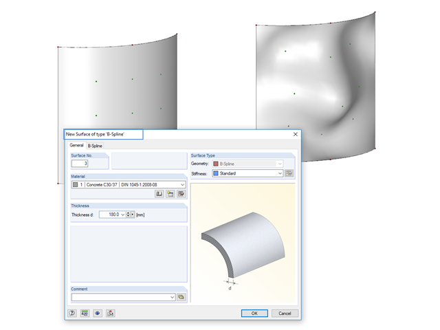
Instead of a quadrangular surface, you can use a B‑spline surface. The shape of this can be adjusted retrospectively, using the integrated help nodes. Depending on the necessary surface complexity, you can create a B‑spline surface with 3 × 3 or 4 × 4 help nodes.
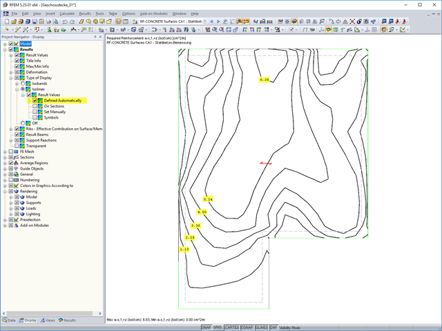
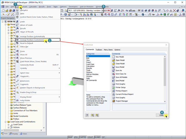
The results of an FEM calculation are usually documented by means of isobands and isolines in the graphical display of results. In the following, we will look at creating the results graphic for the black-and-white printout.

When calculating foundations according to EC 7 or EC 2, different foundation types or sizes are usually used in one object. However, boundary conditions like the soil parameters, the materials for foundations, concrete covers, and the load combinations selected for design remain the same for all foundations, as a rule.

In RF‑/FOUNDATION Pro, the reinforcement to be placed in the foundation slab and, if necessary, the bucket links, is displayed in a 3D rendering and in the reinforcement drawings.

In the RF-/FOUNDATION Pro add-on module, you can select the automatic dimensioning of the foundation plate geometry. In the dialog box for the design parameters of the foundation plate, you can, for example, specify the increment for the increase of the base area and the foundation plate thickness. You can also automatically increase the covering for a stabilizing effect of the geotechnical designs.
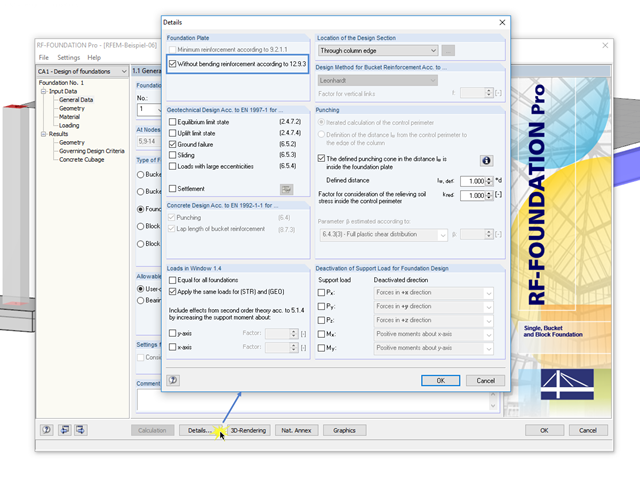
In RF-/FOUNDATION Pro, you can also calculate unreinforced foundation plates according to Section 12.9.3 of EN 1992-1-1 [1]. To do this, select the "Without bending reinforcement according to 12.9.3" check box in the "Foundation Plate" section of the "Details" dialog box.

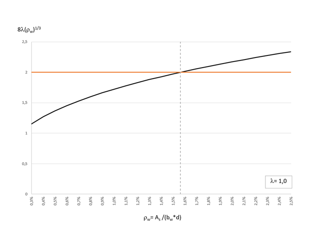
The shear force resistance VRd,c without computational shear force reinforcement according to 6.2.2 of EN 1992-1-1 [1] or 10.3.3 of DIN 1045-1 [2] is calculated depending on the longitudinal reinforcement ratio. If the required longitudinal reinforcement from the bending design is used for the calculation of VRd,c, this leads to an underestimation of the shear force resistance without shear reinforcement in the vicinity of the hinged end supports. In contrast to the shear force, the required bending reinforcement decreases in the direction of the support. Furthermore, the actually inserted longitudinal reinforcement usually deviates significantly from the required bending reinforcement in the end support area (for example, in the case of non-staggered beam reinforcement).
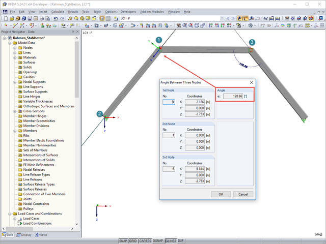
To determine the distance between two nodes or the angle between two objects without using the dimensioning function, you can simply use the "Measure" option on the "Tools" menu. Here, you can also choose between various measure functions.
The description of load cases, load combinations, or result combinations is often longer than fits into the drop‑down combo box "Current Load Case, Load Combination, Result Combination or Module Case" in the toolbar of RFEM or RSTAB.
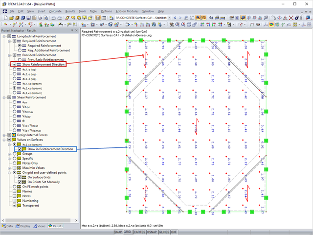
In RF‑CONCRETE Surfaces, the design of the surface reinforcement is done by means of a freely definable reinforcement mesh. In RF‑CONCRETE Surfaces, you can display the reinforcement direction by activating the reinforcement arrow that represents it.
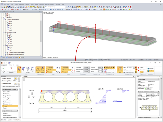
Prestressed concrete slabs consist of composite, uniaxially stressed hollow plates with a width of about 1.20 m. These elements are prestressed with pre-tension in a precast concrete plant. The precasting is usually done with slipformers. Due to the lesser self‑weight of the non‑solid slab and the existing prestress, these precast prestressed hollow core slabs show a lower deflection than loosely reinforced slabs made of solid concrete.

In Part 1, the selection of the design criteria for dimensioning the reinforcement for the serviceability limit state design in RF‑CONCRETE Members and CONCRETE was explained. Now, we go into detail for the function "Find economical reinforcement for crack width design".
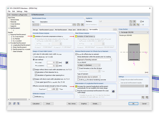
The RF-CONCRETE Members and CONCRETE add-on modules provide the option for "Dimensioning of Longitudinal Reinforcement for Serviceability Limit State". You can select the design criteria for the calculation of the longitudinal reinforcement.

When defining the effective slab width of T-beams, RFEM provides the predefined widths that are determined as 1/6 and 1/8 of the member length. A more detailed explanation on these two factors is given below.

To cover the required transverse reinforcement, RF‑CONCRETE Members and CONCRETE determine the most cost-efficient transverse reinforcement as a reinforcement proposal in accordance with the predefined stirrup diameter.
The most recent standard ACI 318‑19 redefines the long-term relation for the determination of the concrete shear resistance Vc. With the new method, the member height, the longitudinal reinforcement ratio, and the normal stress now influence the shear strength, Vc. This article describes the shear design updates, and the application is demonstrated using an example.

Describing the procedure for the serviceability limit state design of a floor slab made of steel fiber reinforced concrete. This article shows how to perform the corresponding design for the SLS by means of the iteratively determined FEA results.

Steel-fiber-reinforced concrete is mainly used nowadays for industrial floors or hall floors, foundation plates with low loads, basement walls, and basement floors. Since the publication in 2010 of the first guideline about steel-fiber-reinforced concrete by the German Committee for Reinforced Concrete (DAfStb), a structural engineer can use standards for the design of the steel fiber-reinforced concrete composite material, which makes the use of fiber-reinforced concrete increasingly popular in construction. This article describes the nonlinear calculation of a foundation plate made of steel fiber-reinforced concrete in the ultimate limit state with the FEA software RFEM.